

Final Project: Under the Rose
Our initial idea:
My group members were Christie, Angie, and Sophie. We wanted to create a safe space where people could release their stress and inner emotions. Our plan was to create a confession box with a "magic" lamp microphone that distorts audio as you speak into it. We also wanted to have a printer that would print questions to help people who don't know what to say.


Materials/Building our Project:
We had initially bought a lamp from a thrift store and decided to modify it so that the microphone would go at the top. We had originally wanted the lamp to be rubbed and the microphone begins to record. We tried using a capacitative sensor by adding some electrical tape to it. It was very finicky so we decided to drop the idea and use buttons instead. We wanted it to be transparent because we wanted to add three different lights for 3 different buttons. Red for recording, Blue for stopping, and white for playing the distorted audio. We decided to get rid of the lamp and create our own as it was very hard to place the lights and all the wires from the breadboard.


Sophie has a lot of experience in modeling and fabrication, so she created a new design to fit all of our needs. We laser cut some acrylic and used leftover wood to create the base for the lamp. We inserted three little LEDs to illuminate it but then we decided to get three different fairy lights so it would illuminate better. We also wanted to create button from the laser printer to show what each button is suppose to do.

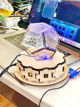

We bought some transparent luminescent acrylic and use some white acrylic for the base. Once we had our prototype. We had people test it out and most people said they would love to have a delete button for extra protection. We hadn't thought much about how this would effect the user's experience. We decided to add an extra button to the magic lamp to include a delete button.
Setting up the confessional:


Electric Printer:


We came up with 2 lists of 10 questions: Deep and more light. We wanted the printer to print two random questions from these two lists by implementing the random function. Due to the lack of time and processing, we weren't able to create a code that would implement it. We decided to use the printer to create a souvenir for people that participate in the experience instead.
Final Result:


Lab: I2C Communication with a Time-of-Flight Distance Sensor
I was really excited to work with this 12C communication lab because I have always been interested in working with light proximity sensors. I had to borrow an Arduino from the shop as mine hasn't come in yet. I used the Arduino BLE and they also didn't carry the VL53L0X distance sensor breakout board. So I used a proximity light sensor instead.The pins were almost identical so i had no issues setting up the breadboard. It wouldn't seem to work. I kept getting "Sensor not responding. Check wiring." but I triple checked it and it still didn't work. I also tried including the the input pins in the code, and it still didn't work. If you have any ideas lmk!


Lab: OLED Screen Display using I2C


I was able to find all the components and it actually worked! It was super fun to work with display. The only issue is that the sensor is a bit wonky and it might not work as well. I am not sure if it's a breadboard issue or the potentiometer is not working as well. Overall, super cool monitor and I will possibly use it for future projects.
Lab: Two-Way (Duplex) Serial Communication Using An Arduino and the p5.webserial Library


I was having trouble having the sensors work with the computer. I tried 2 different sensors and finally it worked. 3 different numbers showed in the serial monitor.


After connecting my board to the p5.js editor, I noticed that the button feature didn't work. I tried pressing it to make the circle disappear and I couldn't figure out what in the code didn't work. Also, even though the potentiometers had an effect on the circle's movement, I initially thought it was two different circles because it constantly was vibrating.

I tried replacing the sensors with pushbutton to see if it would have a better, if any effect on the sketch and it didn't really change anything. I think I need a new arduino or board.
Playing with Asynchronous Serial Communications
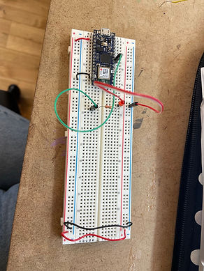
I connected two potentiometers to analog pins A0 and A1, and one pushpin to digital pin D2. I had no trouble connecting the 1st potentiometer and got a reading right away on the serial monitor when I controlled the potentiometer from 0 to 255. I then tried the Serial.write() function and it freaked me out. I still don't understand the reasoning behind it.

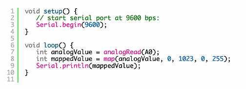

After using one potentiometer, I connected the other, and I found it super helpful to know that you can control each one independently of one another. I changed the code and played around with both for a bit. Then I also connected the push pin which showed as either 1 or 0.


Using the p5.webserial Library!
Initially I was having a bit of trouble as I pasted the code in the draw() function but it was so fun to use once I figured it out. I connected one potentiometer was able to read the sensor value on the screen, which was very entertaining. The sketch that was being drawn had a little bit of a delay but it still worked.


Light turn on!

The third lab is the one I had the most trouble with as the light refused to turn on despite it showing a change in the p5.js preview. It also struggled to work, but I checked the board and the code and I still don't understand.
Midterm Project: Scary DollHouse
Planning Stage:
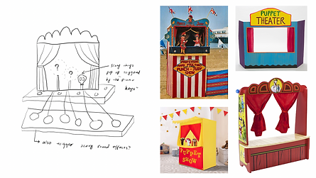
We had initially thought about creating a scary piano. With the keys being the squish dolls and having a scary figure appear on the screen. When we showed the class this idea and our plan B: a scary dollhouse of some sort, the scary dollhouse won. We decided to make three buttons that perform different functions: one that lifts the characters, another that turns on the stage lights and starts creepy music, and a secret spray bottle that sprays the characters with fake blood. We were able to make 3/4 functions that we wanted.

Building the Doll House and Characters:
We had initially thought to use cardboard to create the characters, but then we quickly realized it wasn't sturdy enough and it wasn't a very clean cut with the exacto knife so we decided to make an outline on illustrator and laser cut the characters. We decided to buy wood to build the dollhouse. We used the saw cutter in the workshop to cut the slabs of the house.


Fabrication: Decorating the house and assets:
We decided to spray paint the dollhouse and decorate it as if it were a forest. We picked up branches around campus and grabbed some tree bark for the decorations. This was definitely my favorite part of the project.


Spray Bottle... the Three Day Battle...
We had the ambition to try and use a servo motor and string to power a red paint colored spray bottle. We tried to many different things until we finally succeeded. Initially we just used the servo motor wings, but we quickly realized it wouldn't work because of how small the wingspan was. We used the laser cutter to cut wing extensions and drill them to the wings. We also used hot glue to paste it behind the bottle.


Even though it was working, once we put in the paint/water mixer in, it got stuck in the spray bottle and it wasn't working anymore. I decided to get another easier to work with spray bottle from Target, and used food coloring instead, and it worked perfectly.


Characters move up and down... if they feel like it.
Our last component of our project was rising the characters with a press of the button. We initially thought to use the DC Motor to pull the characters, but then decided to use the servo motor as it would give us more control. We used millis to control the time the servo motor pulled and dropped the characters. We decided to connect them with some plastic and because the man was heavier than the woman, it weighed it down. We glued a nut to make it weigh more and used strings to balance it. It decides to work sometimes, but do to undetermining factors, it sometimes gets the string stuck.


FINAL RESULT:

Motor powered by DC Power supply
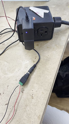
I tried following the instructions on the lab, but there were two problems: I didn't have a DC power supply and when I found one it was too high in voltage (12V). In order to reduce the amount of voltage, I used a LM7805 resistor so the board wouldn't blow up. I used the code provided and made sure it was using the right pin numbers. Once I plugged in the code, it spun a lot quicker.


I tried to complete this lab, but I triple checked the code and wiring and it still did not work. Olive told me that I didn't need the DC power supply so I tried running the code without it and still no luck.

Sensors, Sound, & a Speaker


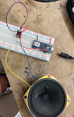
To create this sensor controlled speaker circuit I initially tried using a sensor, but then opted out to use a phototransistor instead. I ran into a couple of issues, as the sound would come out very faint. I fixed this by changing my original 100 ohm resistor to a 68 ohms one. I also changed the sensors ranges from the recommended minimum of 200 to 50 and recommended most from 900 to 500. This allowed the speaker to let out a louder distinct sound.

Let's create some Music!
In the earlier project, I was struggling with making the speaker louder, but then I realized that I could've used a transistor to make it louder. I used the same 68 ohm resistor and then used a TIP120 transistor. It made a MASSIVE difference.
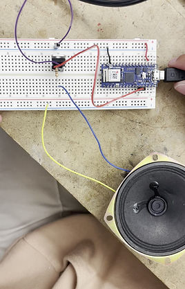
Now it was time to actually create some music. I first started by downloading a 2nd tab of texts called pitches.h. This would reference the type of notes I could use.
Initially it didn’t work because I copied the diagram directly and put the wires on the incorrect pins. When I finally was able to put them in the correct pins: A0, A1, A2. I created a int pins [] in the code. We could still not hear it so I changed the threshold to 100.
I still had trouble hearing the sounds so I changed the type of tones so the human ear could hear it. To further increase the loudness, I used the same TI120 transistor. I am so excited to create more music.


MOTORS... MOTORS... MOTORS...
To create this motor, I decided to use a force-sensing resistor. I checked the range and realized it was a little too high. I changed the ranges from 1000 to 930, and left it at zero. It finally reacted to the sensor, but then I wanted it to work even better and I lowered the motor range as well.
I wanted to experiment with another sensor and I got a phototransistor to replace the force-sensing sensor so the motor could move as it got darker. It worked even better!


Setting up a Breadboard...


In order to setup the breadboard and see how it works. I had to collect a few items from the shop: a resistor, an LED light and a multimeter. I couldn't find a DC power jack, so I connected the arduino to my computer through USB. The arduino was very hard to stick in at first, but by poking it a few times, I was able to connect it. I first started with using two wires to represent the ground and the voltage. I connected the wires from the left to the right of the breadboard. I grabbed two more wires that represent the voltage and ground to connect the arduino's power to the breadboard. The voltage wire is connected to the 3rd throw of the arduino that measures 3.3 volts, which I checked with the multimeter, to the left side red column. I then grabbed another wire and connected the row marked "ground" in the arduino to the right side blue column. I did this because the computer is only able to supply 3.3V of electricity. After that I used a resistor to safetly transfer the energy from the arduino to then light up the LED light. To create a full circuit, I used another wire to connect the LED light to the ground. Once all three connected in the same rows, the light LIT UP!
Switches,Buttons...


When it came time to create switches, I teamed up with Lily and Olive. We first created a switch using a button provided in the kit. We made sure to connect the button to the power supply by using another voltage wire. We then used the resistor to safetly control the transfer of power to the LED light. To complete the circuit, I connected another wire to the ground. The button controls the flow of energy to the LED light, which you can see on the video to the right.
We then wanted to take it a step further and create another type of button. Rose and Lily found another wire used for gift decoration. Using the multimeter we checked to see if it would be a good conductor and it worked well. We wanted to use them as a "switch" to complete the circuit. We cut up two strings and made two rings from them. Shedding off a bit so the wires were exposed. We plugged one string to the ground and the other to the LED light. Once we connected them we completed the circuit, but once we separated them, it turned off the light.


This was the first time that I used a digital output. I used 4 resistors, two 220 ohms resistors for the digital and one of10 kilohms for the analog. I used a wire to connect to digital pin 2 from the same row that connects the resistor and the pushbutton. The connected the 2 LED lights to digital pin 3 and digital pin 4.
I had learned about if then statements before and I was excited to put them into play. In the setup (), I inserted the one input, the pushbutton, and two outputs (the LED lights). Using the if then and else statement, I was able to interchange between the lights.
Red light... Yellow Light...
Potentiometer = Control
I connected the potentiometer to analog 0, and LED connected to the digital pin 9. Programming this in the arduino was a little more complicated. You have to establish some values: one to hold the value returned by the potentiometer, and another to hold the brightness value. Using this code:
I was able to control the brightness level.


Some fun and Sensors:

I was so excited to work with sensors. It was very difficult at first because I had to change the right sensor value from 400 to 0 as it wouldn't detect a massive change. It also didn't initially work because I had put the wrong pin number for the 2nd LED light, but I was immediately able to change it back in the code.